HDLC (High-level Data Link Control):
HDLC is a bit-oriented synchronous data link layer protocol developed by ISO and designed to support both half-duplex and full-duplex communication over point-to-point and multipoint links. But is now used almost exclusively to connect one device to another, using what is known as Asynchronous Balanced Mode (ABM). The original master-slave modes Normal Response Mode (NRM) and Asynchronous Response Mode (ARM) are rarely used. HDLC provides both connection-oriented and connectionless service.
Three types of stations à Primary, secondary, and combined stations.
- Primary stations are used in Unbalanced configuration.
- Secondary station combined with primary station and used in Symmetrical configuration.
- Combined station used in Balanced configuration.
Modes of communication à Three types
1. Normal Response Mode (NRM) - refers to the standard primary- secondary relationship. The secondary device must have permission from the primary device before transmitting.
2. Asynchronous Response Mode (ARM) – A secondary may initiate a transmission without permission from the primary.
3. Asynchronous Balanced Mode (ABM) – All stations are equal. Either combined station may initiate transmission with the other combined station without
permission.
HDLC operations, and Frame Types
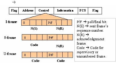
There are three fundamental types of HDLC frames.
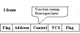
- Information frames, or I-frames, transport user data from the network layer. In addition they can also include flow and error control information piggybacked on data.
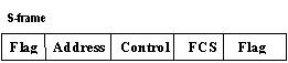
- Supervisory frames, or S-frames, are used for flow and error control whenever piggybacking is impossible or inappropriate, such as when a station does not have data to send. S-frames do not have information fields.
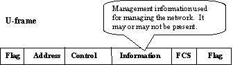
- Unnumbered frames, or U-frames, are used for various miscellaneous purposes, including link management. Some U-frames contain an information field, depending on the type.
HDLC frame Fields
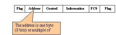
Address
à The address field may contain one byte or a multiple of bytes. If one byte address than the last bit is ‘1’. If multiple byte address then every last bit of byte must ‘0’ indicates some bytes are following and last bytes last bit must be ‘1’, shows end of address.
Control
à
Information
à The information field contains the user’s data in an I-frame, and network management information in a U-frame.
FCS Field
à The frame check sequence is HDLC’s error detection field. It can contain either a two or four byte CRC.
Piggybacking means combining data to be sent and acknowledgement of the frame received in one single frame.
Bit snuffing means every time a sender wants to transmit a bit sequence having more than five consecutive 1’s, it inserts one redundant 0 after the fifth 1.